Bit Twiddling Synthesis
Yes indeed, what we have here is another 'off-the-wall' way to synthesize sounds. Like so:
a) Generate a standard sine wave that swings in the range [-1,1]
b) Convert each sample value of the sine wave to an integer that can be represented on the bits of one byte
c) Perform conditional and unconditional operations on the bits like shift them, re-arrange them, flip them and so on
d) Convert the 8 bit pattern back to a sample value, and output the waveform
My objective was firstly to see what kind of complex wave shapes could be created like this, and secondly, to discover whether the method is capable of introducing movement to the waveforms it generates, in some intuitive way. A link to the sounds is in the 'Results' section.
Background
When I first considered the possibilities of BTS, a fellow synthesis enthusiast remarked 'But there's only so much you can do with 8 bits', and that's when I took up the challenge to see not only how many different waveforms I could produce with operations on 'just 8 bits', but determine whether any kind of dynamic variation to the sound was possible with BTS. After all, no matter how many harmonics a generated waveform may be jam-packed with, if you can't evolve the sound as it plays with the synthesis technique in question, interest in both the sound and the synthesis method is bound to wane quickly. Quite simply, movement is an essential aspect of sound design. When a piano key is struck for example, we expect sound motion throughout the length of the note; the initial sound is very 'bright' and becomes 'duller' as it dies away (a traditional subtractive synth simulating a piano sound would achieve this effect through the use of a filter). With this in mind, I roughly assembled an application for experimenting with BTS in PureBasic. Then, based on initial results obtained through the trial and error of various bit operations, I 'formalized' the architecture and GUI of the application, played it with a virtual midi keyboard, and have captured its outputs for presentation and discussion.
*SPOILER ALERT* The sonic and visual contrast between a humble sine wave and the results after 'twiddling its bits', is like the difference between where I'm standing and what's on either side of me:

Bit Twiddling Synthesizer Download
| btssynthv101install.zip |
Simply unzip the contents of this file into any directory on your hard drive, and double-click on 'BitTwiddlingSynth101.exe' to launch the application. The zip also contains the application source in a .txt file, and the .PB PureBasic (v4.6) project files.
System Requirements
Minimum Hardware: Intel Pentium 2, 500MHz. 512MB RAM
Operating System: Windows 2000, XP, 7. I have successfully installed and run the application on these platforms, but should also work with Windows Vista.
Operating System: Windows 2000, XP, 7. I have successfully installed and run the application on these platforms, but should also work with Windows Vista.
Application Overview
A traditional 'subtractive synth' can be thought to consist of:
i) A source of sound
ii) A modifier section which processes the output of the source
The sound source typically produces simple waveshapes such as sawtooth and pulse which are easy to describe mathematically and generate electronically, and which contain all the required harmonic content for the final sound. The modifier comprises at least a filter to 'subtract' any harmonics that aren't required, and an amplifier to shape the sound's volume, and both of these are generally controlled by Envelope Generators - such as ADSRs.
Some subtractive synths feature a single ADSR which controls both the opening and closing of the filter, and the volume of the sound over time. I constructed the BTS test application also with one ADSR, and although it too determines the final level of the sound (the overall amplitude of the signal after bit manipulation is performed), that's where the similarity with a traditional subtractive synth ends. The BTS test application has no filter, as the intent was to see whether timbral variation in the sound could result from a change in signal level PRIOR to the bit manipulation. Furthermore the BTS application features only one simple sound source - a sine wave - as the intent was for operations on the bits of the sine wave to produce a diversity of waveforms.
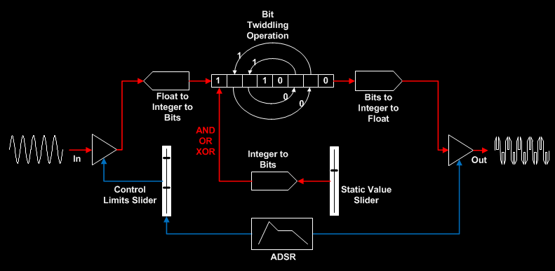
In the following schematic of the BTS application, the blue lines depict the ADSR affecting the amplitude of the signal before and after the bit manipulation (in the before case, the upper and lower amplitude limits within which the ADSR operates are set by means of a 'Control Limits' slider, and in the after case, the ADSR operates between the maximum amplitude 1 and minimum amplitude 0). The red lines show the 'core' BTS signal path. The Static Value slider sets a value between 1 and 100 for use by three of the thirteen types of bit manipulation operations that were tried (the remaining operations did not use this facility):
i) A source of sound
ii) A modifier section which processes the output of the source
The sound source typically produces simple waveshapes such as sawtooth and pulse which are easy to describe mathematically and generate electronically, and which contain all the required harmonic content for the final sound. The modifier comprises at least a filter to 'subtract' any harmonics that aren't required, and an amplifier to shape the sound's volume, and both of these are generally controlled by Envelope Generators - such as ADSRs.
Some subtractive synths feature a single ADSR which controls both the opening and closing of the filter, and the volume of the sound over time. I constructed the BTS test application also with one ADSR, and although it too determines the final level of the sound (the overall amplitude of the signal after bit manipulation is performed), that's where the similarity with a traditional subtractive synth ends. The BTS test application has no filter, as the intent was to see whether timbral variation in the sound could result from a change in signal level PRIOR to the bit manipulation. Furthermore the BTS application features only one simple sound source - a sine wave - as the intent was for operations on the bits of the sine wave to produce a diversity of waveforms.
In the following schematic of the BTS application, the blue lines depict the ADSR affecting the amplitude of the signal before and after the bit manipulation (in the before case, the upper and lower amplitude limits within which the ADSR operates are set by means of a 'Control Limits' slider, and in the after case, the ADSR operates between the maximum amplitude 1 and minimum amplitude 0). The red lines show the 'core' BTS signal path. The Static Value slider sets a value between 1 and 100 for use by three of the thirteen types of bit manipulation operations that were tried (the remaining operations did not use this facility):
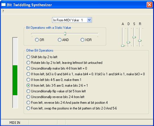
BTS Operations
The following 'bit twiddles' were tried, and are available as choices via the BTS application GUI:
1. Shift two bits to the left* eg 11011001 becomes 01100100
2. Rotate two bits to the left, while keeping first bit from left intact* eg 11011001 becomes 11100110
3. AND bits with a static bit pattern* eg 11011001 AND 00111000 = 00011000
4. OR bits with a static bit pattern* eg 11011001 OR 00111000 = 111110011
5. XOR bits with a static bit pattern* eg 11011001 XOR 00111000 = 11100001
6. Keep the first four bits from left intact, and make the next four bits always 0 eg 11011001 becomes 11010000
7. If from left, third bit is 0 and fourth bit is 1, make fourth bit 0. Else, if third bit is 1 and fourth bit is 1, make third bit 0. If neither condition is true, then two variants: output 0 bit pattern or output original bit pattern eg 11011001 becomes 11001001
8. If the value of the bit pattern is positive: then if fourth and fifth bits from left are 0, make them both 1, otherwise output 0 bit pattern. If the value of bit pattern is negative: always output a 0 bit pattern* eg 11000101 becomes 00000000 but 01000101 becomes 01011101
9. If from left, third, fourth and fifth bits are 0, make from left bits two to six 1, otherwise, output original bit pattern eg 11000101 becomes 11111101
10. Unconditionally flip the fifth bit from left* eg 11011001 becomes 11010001
11. Reverse the three bits two to four from the left eg 11000101 becomes 10010101
12. From left, reverse the three bits two to four, and paste them at position four in the bit pattern eg 11000101 stays as 11000101
13. Swap the positions in the bit pattern of, from left, bits two to three and five to six eg 11000101 becomes 10101001
The asterisked operations in this list were implemented using binary arithmetic commands native to the programming language (PureBasic), without first converting the bit pattern into a string and doing the manipulations as sub-strings. For example, let us say the value of each sample of the sine wave is held in variable osc1val.f Then:
To shift two bits to the left:
Osc1BinaryVal.b = (osc1val)*127
Shifted.b= Osc1BinaryVal<<2
newosc1val.f = Shifted/127
To unconditionally flip fifth bit from the left:
Osc1BinaryVal.b = (osc1val)*127
mask.b = 1
Flipped.b = Osc1BinaryVal ! (mask <<3)
newosc1val.f = Flipped/127
An example of a non-asterisked operation (where the bit manipulations were performed as strings), is 'Reverse the three bits two to four from left', as follows::
Osc1BinaryVal.b = (osc1val)*127
Osc1BinaryAsString.s = RSet(Bin(Osc1BinaryVal, #PB_Byte), 8, "0")
Thesub.s = ReverseString(Mid(Osc1BinaryAsString, 2, 3))
reassembled.s = "%" + Mid(Osc1BinaryAsString, 1,1) + Thesub + Mid(Osc1BinaryAsString, 5, 4)
reassembledval.b = Val(reassembled)
newosc1val.f = reassembledval/127
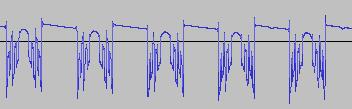
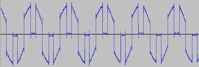
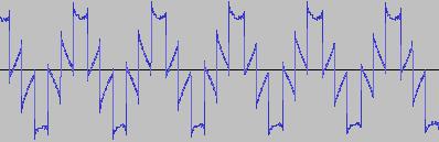
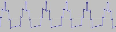
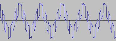
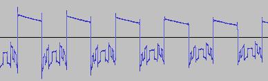
In all such string-based bit manipulation cases, it was found the waveform could be made to change substantially if:
The PureBasic constant #PB_Byte is omitted when converting the bit pattern to a string prior to the bit manipulation (#PB_Byte specifies that the number to be converted into a string is a byte number ranging from 0 to 255, and not a quad number)
and/or
The variable holding the value of the bit pattern after bit manipulation is performed, is NOT explicitly cast as a byte type (which can take a value in the range -128 to +127) ie if in the example above the expression is written as reassembledval = Val(reassembled), instead of reassembledval.b = Val(reassembled)
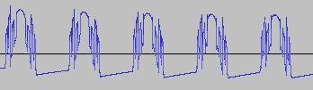
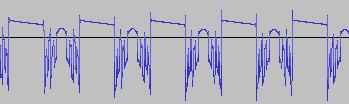
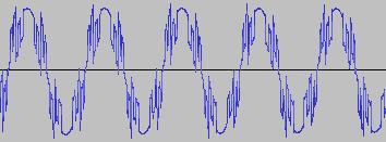
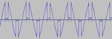
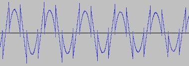
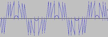
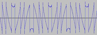
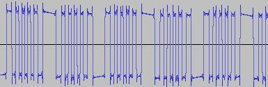
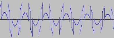
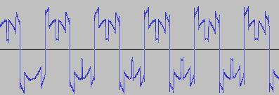
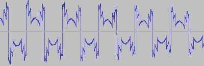
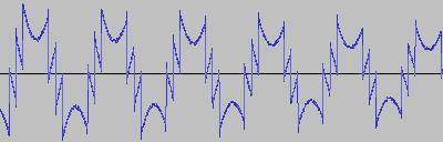
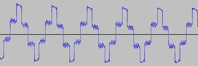
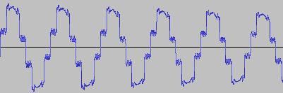
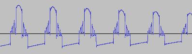
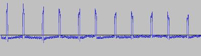
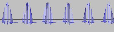
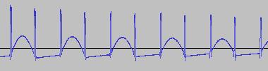
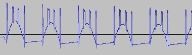
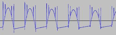
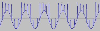
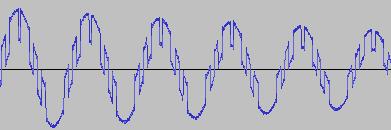
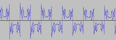
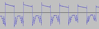
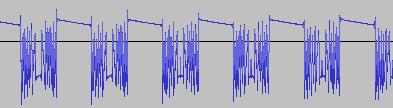
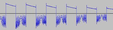
As can be seen from below waveforms, such modifications when applied to the 'Reverse the three bits two to four from left' example, allow 'gapped/rectified' waveforms and waves with 'alternating shapes' (different shapes concatenated in sequence) to be created:
1. Shift two bits to the left* eg 11011001 becomes 01100100
2. Rotate two bits to the left, while keeping first bit from left intact* eg 11011001 becomes 11100110
3. AND bits with a static bit pattern* eg 11011001 AND 00111000 = 00011000
4. OR bits with a static bit pattern* eg 11011001 OR 00111000 = 111110011
5. XOR bits with a static bit pattern* eg 11011001 XOR 00111000 = 11100001
6. Keep the first four bits from left intact, and make the next four bits always 0 eg 11011001 becomes 11010000
7. If from left, third bit is 0 and fourth bit is 1, make fourth bit 0. Else, if third bit is 1 and fourth bit is 1, make third bit 0. If neither condition is true, then two variants: output 0 bit pattern or output original bit pattern eg 11011001 becomes 11001001
8. If the value of the bit pattern is positive: then if fourth and fifth bits from left are 0, make them both 1, otherwise output 0 bit pattern. If the value of bit pattern is negative: always output a 0 bit pattern* eg 11000101 becomes 00000000 but 01000101 becomes 01011101
9. If from left, third, fourth and fifth bits are 0, make from left bits two to six 1, otherwise, output original bit pattern eg 11000101 becomes 11111101
10. Unconditionally flip the fifth bit from left* eg 11011001 becomes 11010001
11. Reverse the three bits two to four from the left eg 11000101 becomes 10010101
12. From left, reverse the three bits two to four, and paste them at position four in the bit pattern eg 11000101 stays as 11000101
13. Swap the positions in the bit pattern of, from left, bits two to three and five to six eg 11000101 becomes 10101001
The asterisked operations in this list were implemented using binary arithmetic commands native to the programming language (PureBasic), without first converting the bit pattern into a string and doing the manipulations as sub-strings. For example, let us say the value of each sample of the sine wave is held in variable osc1val.f Then:
To shift two bits to the left:
Osc1BinaryVal.b = (osc1val)*127
Shifted.b= Osc1BinaryVal<<2
newosc1val.f = Shifted/127
To unconditionally flip fifth bit from the left:
Osc1BinaryVal.b = (osc1val)*127
mask.b = 1
Flipped.b = Osc1BinaryVal ! (mask <<3)
newosc1val.f = Flipped/127
An example of a non-asterisked operation (where the bit manipulations were performed as strings), is 'Reverse the three bits two to four from left', as follows::
Osc1BinaryVal.b = (osc1val)*127
Osc1BinaryAsString.s = RSet(Bin(Osc1BinaryVal, #PB_Byte), 8, "0")
Thesub.s = ReverseString(Mid(Osc1BinaryAsString, 2, 3))
reassembled.s = "%" + Mid(Osc1BinaryAsString, 1,1) + Thesub + Mid(Osc1BinaryAsString, 5, 4)
reassembledval.b = Val(reassembled)
newosc1val.f = reassembledval/127
In all such string-based bit manipulation cases, it was found the waveform could be made to change substantially if:
The PureBasic constant #PB_Byte is omitted when converting the bit pattern to a string prior to the bit manipulation (#PB_Byte specifies that the number to be converted into a string is a byte number ranging from 0 to 255, and not a quad number)
and/or
The variable holding the value of the bit pattern after bit manipulation is performed, is NOT explicitly cast as a byte type (which can take a value in the range -128 to +127) ie if in the example above the expression is written as reassembledval = Val(reassembled), instead of reassembledval.b = Val(reassembled)
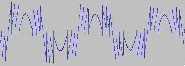
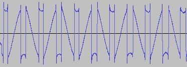
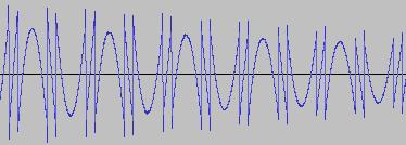
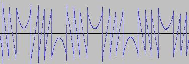
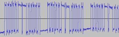
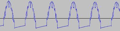
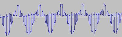
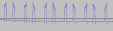
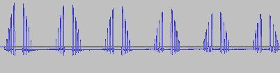
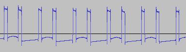
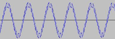
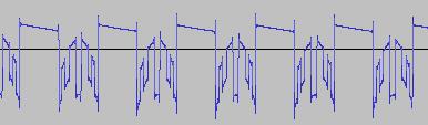
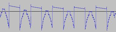
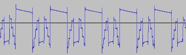
As can be seen from below waveforms, such modifications when applied to the 'Reverse the three bits two to four from left' example, allow 'gapped/rectified' waveforms and waves with 'alternating shapes' (different shapes concatenated in sequence) to be created:
|
Omit #PB_Byte, specify 'reassembledval.b':
|
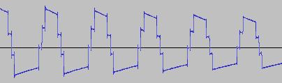
Omit #PB_Byte, specify 'reassembledval':
|
|
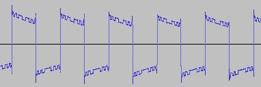
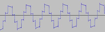
Include #PB_Byte, specify 'reassembledval':
|
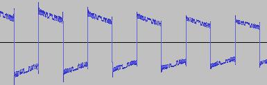
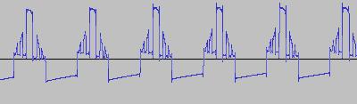
Include #PB_Byte, specify 'reassembledval.b':
|
The application GUI does not expose the ability to include or exclude #PB_Byte or to include or exclude the '.b' suffix (from the variable holding the value of the bit pattern after bit manipulation is performed), but the source code is commented with where this can be done directly.
Results
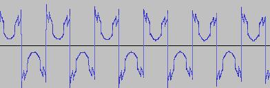
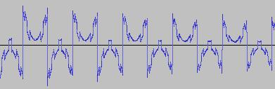
The ADSR was set to a short Attack, and for each waveform generated with each BTS operation, the wave shape at the top of the Attack, and close to the end of the Release, was captured. The snapshots are all shown below. Key observations:
i) In each case, the primary visual difference between the two sets of 'From' and 'To' images is that certain segments are accentuated while others are suppressed, even though the 'basic form' of the waveform is retained. Such a change in shape is sufficient for a timbral difference between the waveform instances to be perceived - not unexpected, since it is possible for even minor changes to a wave shape to produce large changes in the harmonic content.
ii) A common feature of the generated waveforms is that they bristle with sharp edges, which means they are not band-limited and so not aliasing-free. This complexity however does result in their being sonically rich (since the sharper the changes in amplitude over time, the richer the sound tends to be). It is not only this richness which makes them good source material for a subtractive synth, but also the fact that it is unnecessary to mix together a great many 'standard waveform' oscillators to create these waveforms in the first place (since BTS generates them easily).
iii) For most bit operations, varying the position of the 'from' control limit results in a change in the initial shape of the waveform. The extent of the change varies according to the bit operation in question.
iv) If the position of the 'to' control limit is set too far away from the 'from' control limit, 'jumps' are perceived in the sound - in the form of one or more 'abrupt' timbral changes in the sound while it plays. The maximum distance the 'to' control limit can be pushed away from the 'from' control limit which still allows for a 'smooth' timbral change within the limits, varies according to both the bit operation in question, and the position of the 'from' control limit.
v) Different bit operations at certain settings can yield similar-looking waveforms (for example the waveform for XOR with a static value, at certain values of the 'from' and 'to' control limits and certain static value, can look like the waveform for 'unconditionally flip fifth bit from left').
vi) Different-looking waveforms can sound similar (for example 'AND with static value', and 'XOR with static value', at certain settings). Again, not unexpected since the shape of a waveform is not the best guide to its harmonic content.
|
1A. Rotate two bits to the left, while keeping first bit from left intact. Control limits range A
|
From
|
To
|
|
1B. Rotate by two bits to the left, while keeping first bit from left intact. Control limits range B
|
From
|
To
|
|
2A. Shift by two bits to the left. Control limits range A
|
From
|
To
|
|
2B. Shift by two bits to the left. Control limits range B
|
From
|
To
|
|
3A. AND bits with a static value. Control limits range and static value setting A
|
From
|
To
|
|
3B. AND bits with a static value. Control limits range and static value setting B
|
From
|
To
|
|
3C. AND bits with a static value. Control limits range and static value setting C
|
From
|
To
|
|
4A. XOR bits with a static value. Control limits range and static value setting A
|
From
|
To
|
|
4B. XOR bits with a static value. Control limits range and static value setting B
|
From
|
To
|
|
4C. XOR bits with a static value. Control limits range and static value setting C
|
From
|
To
|
|
5. OR bits with a static value. Control limits range and static value setting A
|
From
|
To
|
|
6A. Keep the first four bits from left intact, and make the next four bits always 0 (Omit #PB_Byte)
|
From
|
To
|
|
6B. Keep the first four bits from left intact, and make the next four bits always 0 (Include #PB_Byte)
|
From, To set to same waveshape
|
|
7A. If from left, third bit is 0 and fourth bit is 1, make fourth bit 0. Else, if third bit is 1 and fourth bit is 1, make third bit 0. If neither condition is true, then output 0 bit pattern (Omit #PB_Byte)
|
From
|
To
|
|
7B. If from left, third bit is 0 and fourth bit is 1, make fourth bit 0. Else, if third bit is 1 and fourth bit is 1, make third bit 0. If neither condition is true, then output original bit pattern (Omit #PB_Byte)
|
From, To set to same waveshape
|
|
7C. If from left, third bit is 0 and fourth bit is 1, make fourth bit 0. Else, if third bit is 1 and fourth bit is 1, make third bit 0. If neither condition is true, then output 0 bit pattern (Include #PB_Byte)
|
From, To set to same waveshape
|
|
8A. If the value of the bit pattern is positive: then if fourth and fifth bits from left are 0, make them both 1, otherwise output 0 bit pattern. If the value of bit pattern is negative: always output a 0 bit pattern. Control limits range A
|
From
|
To
|
|
8B. If the value of the bit pattern is positive: then if fourth and fifth bits from left are 0, make them both 1, otherwise output 0 bit pattern. If the value of bit pattern is negative: always output a 0 bit pattern. Control limits range B
|
From
|
To
|
|
9A. If from left, third, fourth and fifth bits are 0, make from left bits two to six 1, otherwise, output original bit pattern (Omit #PB_Byte). Control limits range A
|
From
|
To
|
|
9B. If from left, third, fourth and fifth bits are 0, make from left bits two to six 1, otherwise, output original bit pattern (Omit #PB_Byte). Control limits range B
|
From
|
To
|
|
9C. If from left, third, fourth and fifth bits are 0, make from left bits two to six 1, otherwise, output original bit pattern (Include #PB_Byte)
|
From, To set to same waveshape
|
|
10A. Unconditionally flip the fifth bit from left. Control limits range A
|
From
|
To
|
|
10B. Unconditionally flip the fith bit from left. Control limits set to value B
|
From, To set to same waveshape
|
|
11A. Reverse the three bits two to four from the left (Omit #PB_Byte, specify 'reassembledval')
|
From
|
To
|
|
11B. Reverse the three bits two to four from the left (Include #PB_Byte, specify 'reassembledval')
|
From - same as 11A case
|
To
|
|
12. Reverse the three bits two to four from the left, and paste them at position 4 in the bit pattern (Omit #PB_Byte, specify 'reassembledval')
|
From, To set to same waveshape
|
|
13A. Swap the positions in the bit pattern of, from left, bits two to three and five to six. Control limits range A (Omit #PB_Byte, specify 'reassembledval')
|
From
|
To
|
|
13B. Swap the positions in the bit pattern of, from left, bits two to three and five to six. Control limits range B (Omit #PB_Byte, specify 'reassembledval')
|
From
|
To
|
Conclusion
We've shown that performing various bit operations on a sine wave allow a wide variety of harmonically rich wave shapes to be created, making them a good source of sound for subtractive synthesis. In fact graphically, the set can almost pass as a 'digital art' collection, featuring waveforms with compound sawtooth, triangular, rectangular and curved segments. Dynamically changing the amplitude of the sine wave prior to performing the bit operations both alters the waveform shape by accentuating certain segments and suppressing others, and changes the sound without any perceived 'discontinuities', as long as the range of amplitude change is constrained to certain bounds in each case.
